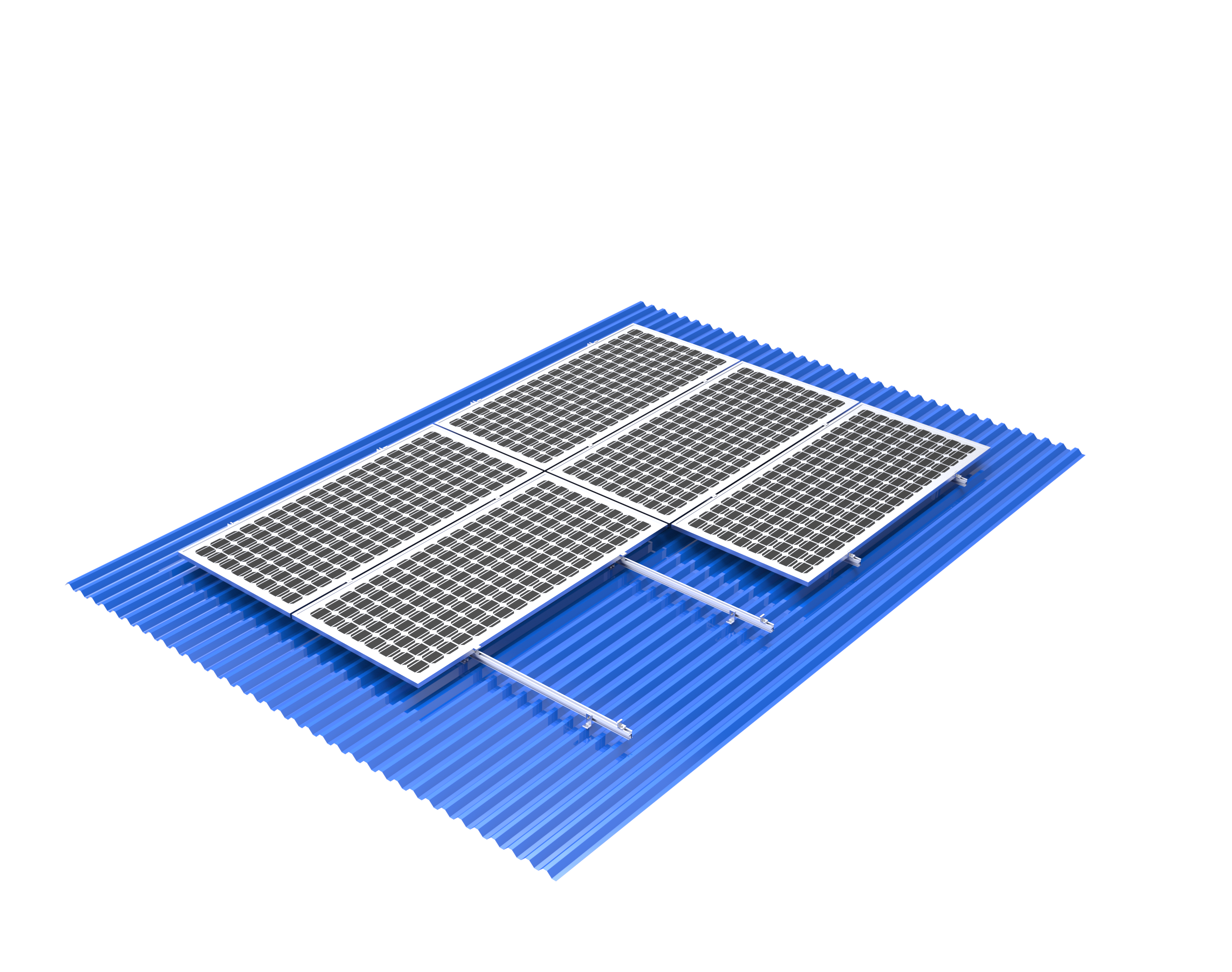
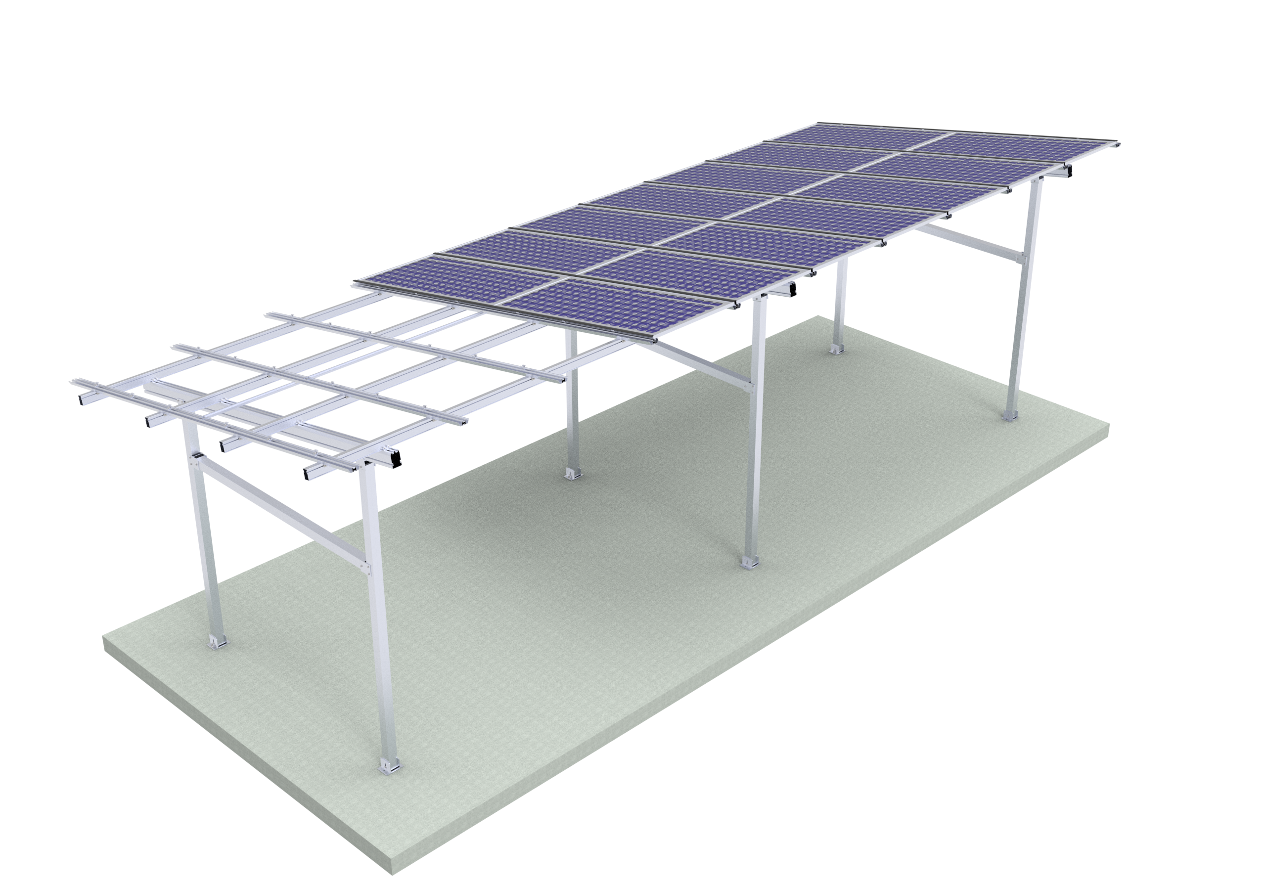
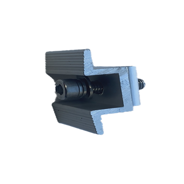
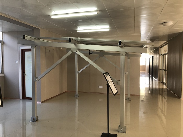
Concrete ballast ground solar mount structures
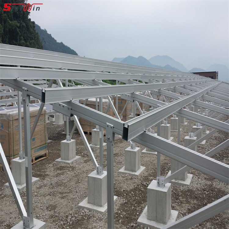
concrete ballast ground solar mount structures, a key solution for commercial and utility-scale solar projects where roof mounting isn't an option and ground penetration is undesirable. What Are Concrete Ballast Ground Mount Systems?
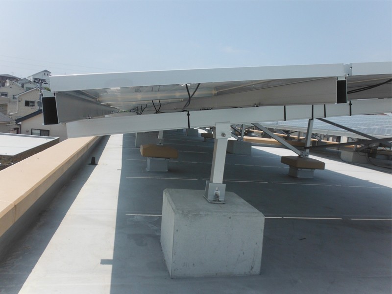
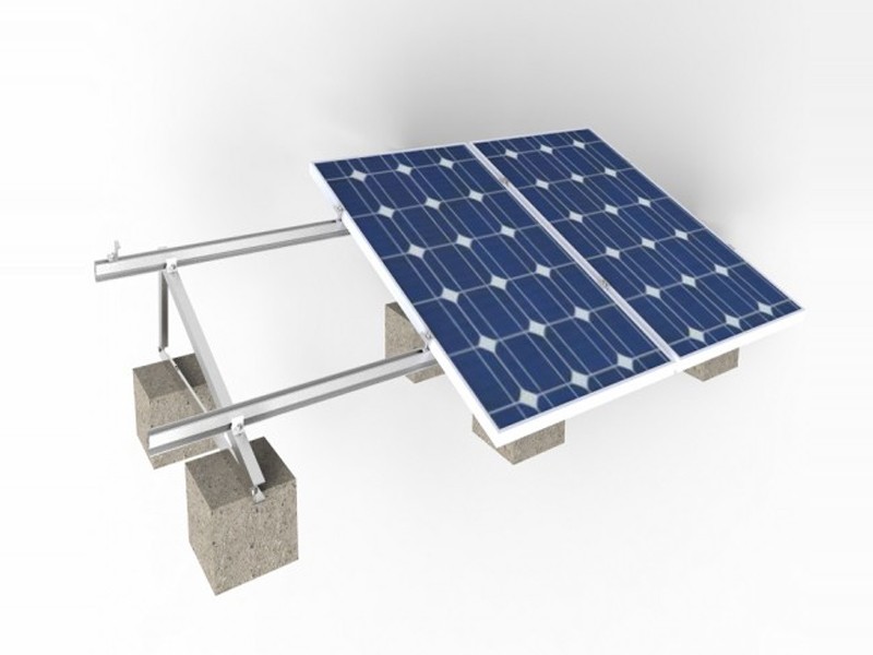
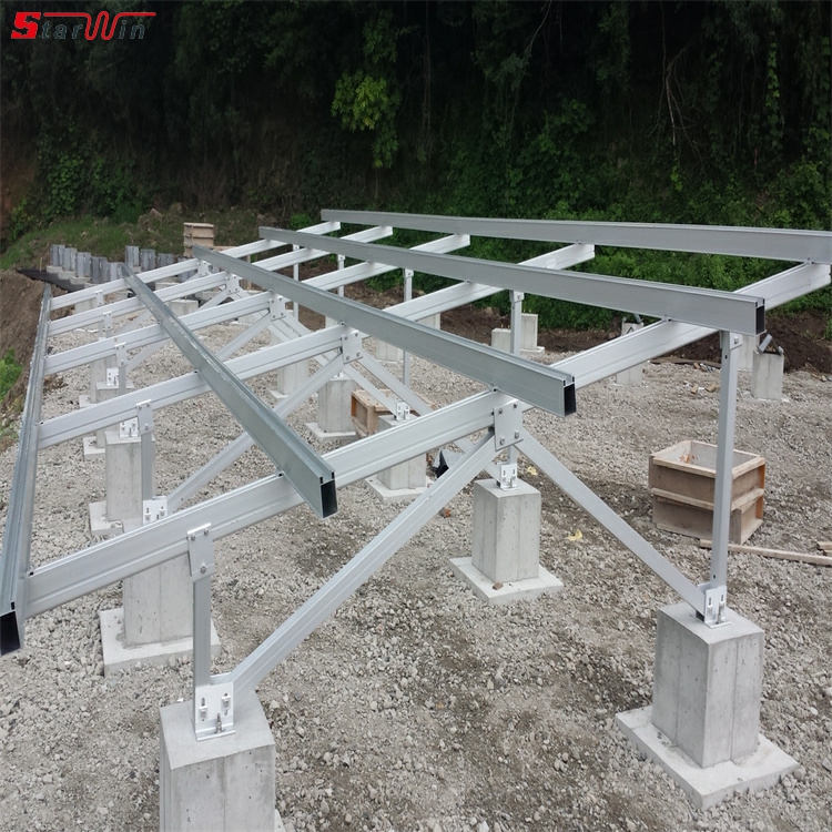
A concrete ballast mount system is a non-penetrating, "weighted-down" foundation for solar arrays. Instead of being anchored into the earth with driven piles or concrete piers, the entire structure is held in place by the sheer weight of concrete blocks.
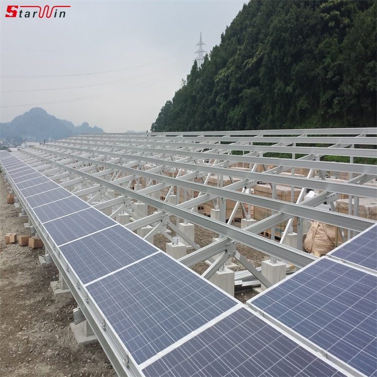
These systems are primarily used in two scenarios:
On Flat or Low-Slope Rooftops: Especially on large commercial buildings with membrane roofs (EPDM, TPO, PVC) that cannot be penetrated. (We'll focus on ground applications, but the principle is identical.)
On the Ground: Where site conditions make traditional drilling or driving difficult, expensive, or prohibited. Core Components of a Ballasted Ground Mount System 1. Concrete Ballast Blocks: These are the "foundation." They can be: • Pre-cast Blocks: Standard concrete blocks (like large cinder blocks) purchased from a supplier. • Custom Cast Troughs: Long, U-shaped concrete troughs that the racking rails sit in. These are common and distribute weight evenly. • Site-Cast Blocks: Concrete poured into forms on-site, which can be more cost-effective for very large projects.
2. Racking Structure: Made primarily of aluminum (for corrosion resistance and weight savings) or sometimes galvanized steel. This includes the rails, purlins, and legs.
3. Ballast Trays / Cradles / Feet: These are the critical interface components. They are typically metal (steel or aluminum) frames or baskets that: • Hold the ballast blocks. • Are attached directly to the racking legs or rails. • Are engineered to distribute the weight of the ballast effectively.
4. Geotextile Fabric (Optional but Recommended): Placed directly on the ground before positioning the ballast blocks. It prevents vegetation from growing up through the array and helps with soil stabilization.
How Ballasted Systems Work: The Engineering Principle The system resists being lifted by wind or moved by other forces through ballast weight rather than foundation depth. • Wind Uplift: The primary force to overcome. As wind flows under and over the tilted panels, it creates a lifting force. The total weight of the concrete ballast must be significantly greater than the calculated uplift force for the site. • Overturning Moment: Wind also tries to push the array over. The weight of the ballast, combined with the wide base of the ballast trays, creates a stabilizing moment that resists this tipping force. • Safety Factor: Engineers design these systems with a large safety factor (e.g., 1.5 or higher).
This means the ballast weight is calculated to be 50%+ more than the maximum expected uplift force. Key Advantages of Ballasted Ground Mounts
1. No Ground Penetration (Biggest Advantage): • Ideal for Contaminated or Remediated Land: Can be built on brownfield sites with caps that cannot be breached. • Avoids Underground Utilities: No risk of hitting electrical, gas, or water lines. • Protects Landfills: Perfect for solar installations on closed landfill caps. • Simplifies Permitting: Often has a simpler permitting process than penetrating systems, as it's not considered a permanent structure in some jurisdictions.
2. Speed and Ease of Installation: • Minimal Heavy Equipment: Requires no pile drivers, auger rigs, or concrete trucks for piers. Installation can often be done with a forklift or small telehandler to place blocks. • Faster Construction: The process is primarily assembly and placement, not excavation and drilling, which can be faster in suitable conditions.
3. Reversibility and Minimal Site Impact: • The system is not permanent. At the end of the array's life, the blocks can be removed and often recycled, and the land is returned to its original state with minimal disturbance.
4. Cost-Effectiveness on Suitable Sites: • On sites with problematic soil (rocky, high water table) or the constraints mentioned above, ballast systems can be significantly cheaper than dealing with complex excavation or specialized drilling.
Key Disadvantages and Design Challenges
1. Soil Bearing Capacity is Critical: This is the most important engineering constraint. The soil must be able to support the immense weight of the concrete without settling unevenly. A geotechnical engineer must test the soil to determine its allowable bearing capacity (e.g., 2,500 psf). Poor soil (e.g., loose fill, clay) can make ballasted systems impossible or prohibitively expensive.
2. High Material and Transportation Costs: • Concrete is extremely heavy. Transporting thousands of concrete blocks to a site is expensive and logistically challenging. • The system uses a much larger amount of aluminum/steel for the racking to create a stable, wide base.
3. Not Suitable for Sloped Terrain: Ballasted systems are designed for very flat ground (typically slopes less than 3-5 degrees). They are impractical on hillsides.
4. Wind Scooping: In high-wind regions, the design must be carefully engineered to prevent wind from getting underneath the array and "scooping" it up. This often requires a very low tilt angle or wind deflectors.
5. Potential for Vegetation Growth: Without proper site preparation (geotextile fabric and gravel), vegetation can grow and lift the ballast trays, compromising stability. The Design and Installation Process 1. Geotechnical Survey: A must-do first step to determine soil bearing capacity. 2. Wind and Snow Load Analysis: An engineer calculates the specific wind uplift and snow loads for the project location using local codes (e.g., ASCE 7).
3. Ballast Calculation: The racking manufacturer or engineer calculates the exact amount of ballast weight required per module or per table to resist the loads, with a safety factor. This dictates the size and number of blocks.
4. Site Preparation: The ground is graded to be perfectly level. Geotextile fabric is laid down, often covered with a layer of gravel for drainage and weed suppression.
5. Layout and Assembly: The racking legs and transverse purlins are assembled on the ground.
6. Ballast Placement: The concrete blocks are carefully placed into the ballast trays or cradles according to the engineered plan.
7. Module Installation: Solar panels are attached to the now-weighted structure. Leading Brands and System Types • Terrasmart: A major player in the US market, known for their ballasted solutions for both ground and roof mounts, often using a "split-rail" system for easier installation. • GameChange Solar: Offers the "Genius Ballast" system, which uses pre-cast ballast blocks and a highly configurable racking structure. • Schletter: A German manufacturer with a global presence, offering robust ballasted systems for various terrains. • Unirac: Provides ballasted solutions for commercial flat roofs, the principles of which are similar to ground mounts.
Conclusion: When to Choose a Ballasted Ground Mount Choose a ballasted system when: • The site has high soil bearing capacity. • Penetration is prohibited (landfills, brownfields, capped sites). • The ground is very flat. • Subsurface conditions are challenging (rock, high water table) making drilling more expensive. Avoid a ballasted system when: • The soil is weak or has a low bearing capacity. • The site is sloped. • The site is remote, and the cost of transporting massive amounts of concrete is prohibitive.
In summary, concrete ballast ground mounts are a highly specialized and invaluable engineering solution that enables large-scale solar development on sites where traditional methods fail, turning otherwise unusable land into a source of clean energy.

